Welcome to the official website of Weifang Haofeng Electromechanical Equipment Co., Ltd!

CONTACT US
Tel:+86-15898948860 / +86-15288998855
E-mail:hfzhuqihang@gmail.com
Company address: Yuhe Subdistrict, Weicheng District, Weifang City, Shandong Province

Hybrid flow cooling tower
Category:
Keywords:
Hybrid flow cooling tower
E-MAIL:
Product details


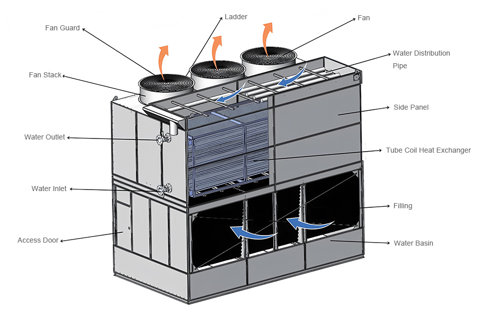
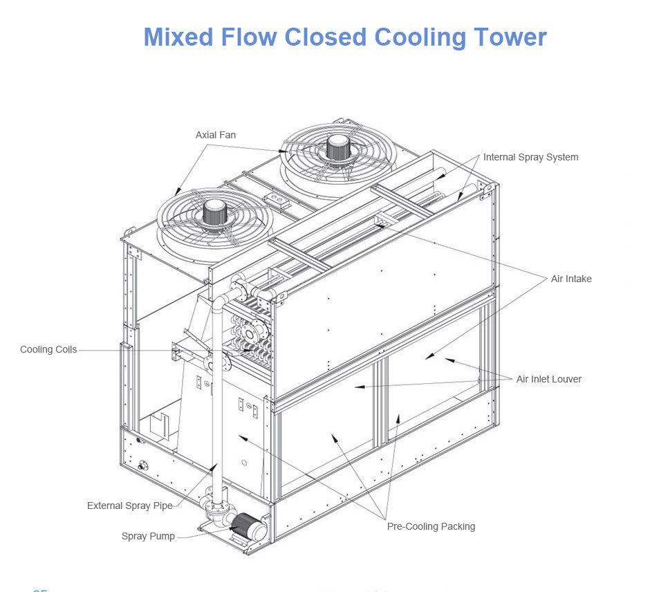
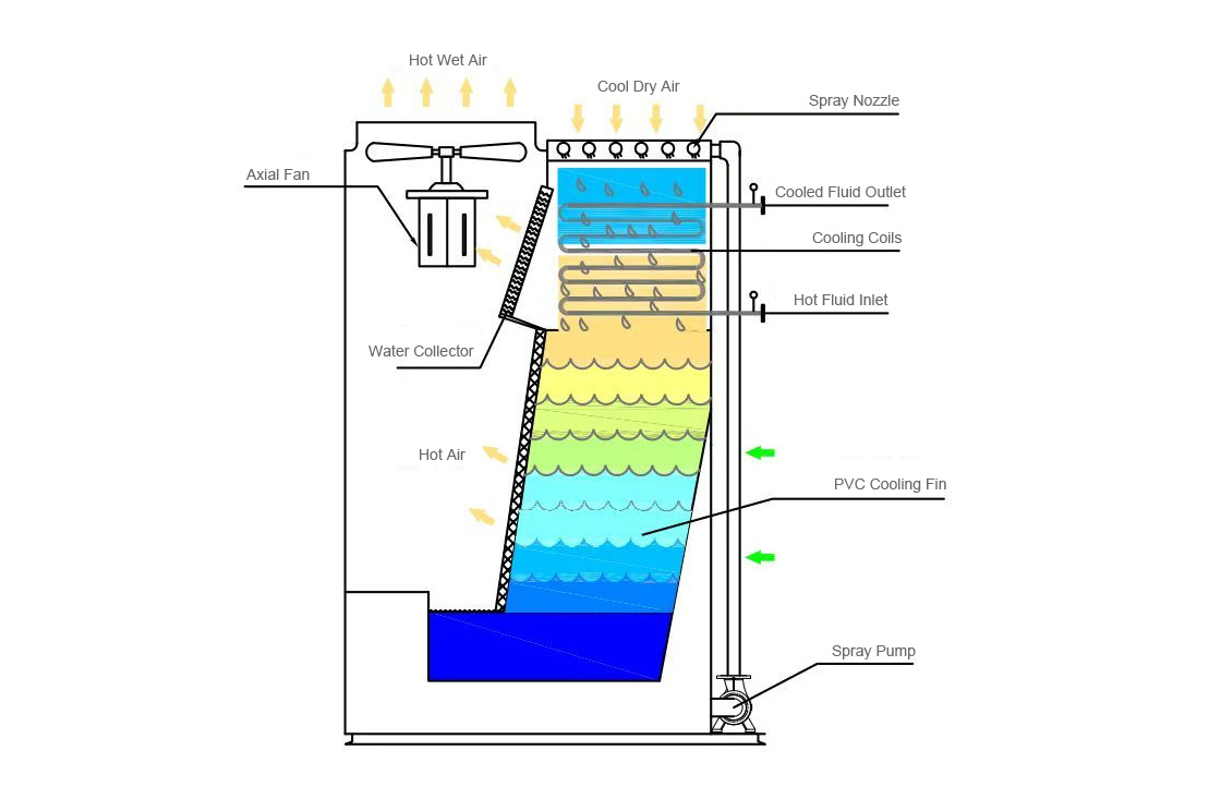
Natural wind enters from two directions. One direction is from the top air inlet of the cooling tower, passing through the cooler and then into the air duct. The other direction is from the inlet grille, passing through the pre-cooling filler and then into the air duct. The air from both directions converges and is discharged upwards from the cooling tower via the exhaust system.
The spray pump draws water from the sump, passes it through the external spray pipe to the internal spray device, sprays it evenly downwards onto the cooler, then onto the pre-cooling filler, and finally into the sump.
The direction of airflow is perpendicular and parallel to the downward direction of the spray water; therefore, it is called a mixed flow closed cooling tower. (Some manufacturers call it a counterflow, using the cooler as a reference object).
Mixed flow closed cooling towers can also be made into double-sided mixed flow closed cooling towers, and cross-flow closed cooling towers can also be made into single-sided cross-flow closed cooling towers.
Our advantages:
1. All the pumps are from Hangzhou Nan Pump Industry, with a three-year warranty.
2. The inlet and outlet liquid pipes of the cooling tower and the flanges are connected by grooved clamps, enabling quick disassembly (facilitating later maintenance and repair).
3. The spray water tank is equipped with a heating device, which automatically heats up in winter when the temperature drops below 2 degrees, preventing the spray water from freezing.
4. The connection pipes of the water tank for the pumps are all made of 304 stainless steel. The entire cooling tower, except for the base channel steel, is made of stainless steel. The valves use turbine connect flange type, making it possible to directly disassemble the pump for later maintenance, and the water in the water tank and the pipes will not leak.
5. The main and backup pumps can automatically switch. The electrical control box has two soft starters to ensure stability and reliability.
6. Our spray pumps are made of stainless steel impellers. (Because the spray water of the cooling tower is usually well water or tap water, with poor water quality, the ordinary cast iron impellers have a very short service life.)
| Model | Cooling capacity (kcal/h) | Main circulation pump | Fan | Spray pump | Connecting pipe (mm) | Equipment Size (mm) | Net weight (Kg) | ||||||
| Power (kw) | Air volume (m³/h) | Power (kw) | Flow rate (m³/h) | Power (kw) | Inlet and outlet | Make-up water inlet | Drain outlet | Length | Width | Height | |||
| HFB-50T | 250000 | 5.5*2 | 22000*2 | 1.5*2 | 53 | 1.1 | DN65 | DN25 | DN32 | 2500 | 2300 | 2800 | 1100 |
| HFB-80T | 400000 | 7.5*2 | 22000*2 | 1.5*2 | 70 | 1.5 | DN80 | DN25 | DN32 | 2800 | 2300 | 2800 | 1400 |
| HFB-100T | 500000 | 11*2 | 22000*3 | 1.5*3 | 80 | 2.2 | DN100 | DN32 | DN32 | 3400 | 2300 | 3000 | 1800 |
| HFB-150T | 750000 | 15*2 | 34000*3 | 2.2*3 | 150 | 3 | DN100 | DN40 | DN50 | 3900 | 2500 | 3000 | 2400 |
| HFB-180T | 900000 | 22*2 | 34000*3 | 2.2*3 | 150 | 3 | DN125 | DN40 | DN50 | 4000 | 2500 | 3300 | 2800 |
| HFB-200T | 1000000 | 22*2 | 35000*3 | 3*3 | 180 | 4 | DN150 | DN40 | DN50 | 4500 | 2500 | 3300 | 3000 |
| HFB-260T | 1300000 | 37*2 | 35000*3 | 3*3 | 233 | 5.5 | DN200 | DN50 | DN65 | 4500 | 2800 | 3300 | 3400 |
| HFB-300T | 1500000 | 37*2 | 35000*4 | 3*4 | 286 | 7.5 | DN200 | DN50 | DN65 | 5000 | 2800 | 3300 | 3900 |
| HFB-350T | 1750000 | 45*2 | 50000*4 | 3*4 | 286 | 7.5 | DN250 | DN65 | DN50*2 | 5500 | 3000 | 3500 | 4500 |
| HFB-400T | 2000000 | 55*2 | 55000*4 | 4*4 | 150*2 | 3*2 | DN250 | DN65 | DN50*2 | 6000 | 3000 | 3500 | 5200 |
| HFB-450T | 2250000 | 55*2 | 50000*5 | 3*5 | 180*2 | 4*2 | DN300 | DN65 | DN50*2 | 7000 | 3000 | 3500 | 6000 |
| HFB-500T | 2500000 | 45*3 | 65000*6 | 4*5 | 233*2 | 5.5*2 | DN300 | DN50*2 | DN50*2 | 7000 | 3300 | 4200 | 6500 |
| HFB-600T | 3000000 | 55*3 | 65000*6 | 4*6 | 286*2 | 7.5*2 | DN300 | DN50*2 | DN50*2 | 8000 | 3300 | 4200 | 7200 |
Note: The above external dimensions are all the dimensions of the host; all model external dimensions can be customized.
The configuration of the auxiliary machine water tank is as follows:
| 50T-100T: 1100-1000-1800 (0.5m³ water tank); 100-200T: 1700-1100-1800 (1.0m³ water tank); Water tank elevated | ||||||||||||
| 180T-260T: 2000-1600-1600 (1.5m³ water tank); 240-300T: 2100-2100-1600 (2.0m³ water tank) Water tank placed horizontally | ||||||||||||
| 320T-400T: 2300-2100-1800 (3.0m³ water tank); 450-600T: 2500-2100-2200 (4.0m³ water tank) Water tank placed horizontally | ||||||||||||
Online consultation
Attention: Please leave your email and our professionals will contact you as soon as possible!
Related products
Counter flow closed cooling tower
Cross flow closed cooling tower
Hybrid flow cooling tower
CONTACT US
Address:Weicheng Economic Development Zone Weifang City Shandong Province.
PRODUCTS


